4-Stroke Gasoline Engine
The four stroke engine was first demonstrated by Nikolaus Otto in 1876, hence it is also known as the Otto cycle. The technically correct term is actually four stroke cycle.
The four strokes of the cycle are intake, compression, power, and exhaust. Each corresponds to one full stroke of the piston, therefore the complete cycle requires two revolutions of the crankshaft to complete.
1) Intake/Induction: During the intake stroke, the piston moves downward, drawing a fresh charge of vaporized fuel/air mixture,
2) Compression: As the piston rises the poppet valve is forced shut by the increased cylinder pressure. Flywheel momentum drives the piston upward, compressing the fuel/air mixture,
3) Ignition/Power: At the top of the compression stroke the spark plug fires, igniting the compressed fuel. As the fuel burns it expands, driving the piston downward, and
4) Exhaust: At the bottom of the power stroke, the exhaust valve is opened by the cam/lifter mechanism. The upward stroke of the piston drives the exhausted fuel out of the cylinder.
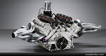
4 Stroke Cycle, 4 Cylinder Engine w/ Overhead Camshafts
4 Stroke Cycle, 4 Cylinder Engine w/ Overhead Camshafts, Valvetrain Animation
4 Stroke Cycle Engine w/ Pushrod Actuated Overhead Valves
2-Stroke Engine
The two-stroke engine consists of only three mobile parts: Piston, connecting rod and crankshaft. The first two-stroke engine was a gas engine invented and built by Etienne Lenoir in 1860. A two-stroke diesel engine was built by Dugald Clark in 1878.
At the point where the sparkplug fires, fuel and air in the cylinder have been compressed, and when the sparkplug fires the mixture ignites. The resulting force drives the piston downward. As the piston moves downward, it is compressing the air/fuel mixture in the crankcase.
As the piston approaches the bottom of its stroke, the exhaust port is uncovered. The pressure in the cylinder drives most of the exhaust gases (but not all) out of cylinder. As the piston finally bottoms out, the intake port is uncovered. The piston's movement has pressurized the mixture in the crankcase, so it rushes into the cylinder, displacing the remaining exhaust gases and filling the cylinder with a fresh charge of fuel.
Now the momentum in the crankshaft starts driving the piston back toward the spark plug for the compression stroke. As the air/fuel mixture in the piston is compressed, a vacuum is created in the crankcase. This vacuum opens the reed valve and sucks air/fuel/oil in from the carburetor. Once the piston makes it to the end of the compression stroke, the sparkplug fires again to repeat the cycle.
2-Strokes vs. 4-Strokes
Advantages of 2 Stroke Engines:
- Do not have valves, simplifying their construction.
- Fire once every revolution (four-stroke engines fire once every other revolution). This gives two-stroke engines a significant power boost.
- Are lighter, and cost less to manufacture.
Disadvantages of 2 Stroke Engines:
- Don't live as long as four-stroke engines. The lack of a dedicated lubrication system means that the parts of a two-stroke engine wear-out faster. Two-stroke engines require a mix of oil in with the gas to lubricate the crankshaft, connecting rod and cylinder walls.
- Two-stroke oil can be expensive. Mixing ratio is about 4 ounces per gallon of gas: burning about a gallon of oil every 1,000 miles.
- Do not use fuel efficiently, yielding fewer miles per gallon.
- Produce more pollution from:
-- The combustion of the oil in the gas. The oil makes all two-stroke engines smoky to some extent, and a badly worn two-stroke engine can emit more oily smoke.
-- Each time a new mix of air/fuel is loaded into the combustion chamber, part of it leaks out through the exhaust port
Diesel Engine
Both diesel engines and gasoline engines covert fuel into energy through a series of small explosions or combustions. The major difference between diesel and gasoline is the way these explosions happen. In a gasoline engine, fuel is mixed with air, compressed by pistons and ignited by sparks from spark plugs. In a diesel engine, however, the air is compressed first, and then the fuel is injected. Because air heats up when it's compressed, the fuel ignites. Rudolf Diesel theorized that higher compression leads to higher efficiency and more power. This happens because when the piston squeezes air with the cylinder, the air becomes concentrated. Diesel fuel has a high energy content, so the likelihood of diesel reacting with the concentrated air is greater. Another way to think of it is when air molecules are packed so close together, fuel has a better chance of reacting with as many oxygen molecules as possible.

The diesel engine uses a four-stroke combustion cycle just like an Otto cycle gasoline engine. The four strokes are:
1) Intake stroke - The intake valve opens up, letting in air and moving the piston down,
2) Compression stroke - The piston moves back up and compresses the air,
3) Combustion stroke - As the piston reaches the top, fuel is injected at just the right moment and ignited, forcing the piston back down, and
4) Exhaust stroke - The piston moves back to the top, pushing out the exhaust created from the combustion out of the exhaust valve.
The diesel engine has no spark plug, it intakes air and compresses it, and it then injects the fuel directly into the combustion chamber (direct injection). It is the heat of the compressed air that ignites the fuel in a diesel engine.
Piston Engine Configurations
Straight or In-Line 4 Cylinder
Flat or Opposed 4 Cylinder
V-6
Radial Engines
The radial engine is a configuration of internal combustion engine, in which the cylinders are arranged pointing out from a central crankshaft like the spokes on a wheel. The pistons are connected to the crankshaft with a master-and-articulating-rod assembly. One piston has a master rod with a direct attachment to the crankshaft. The remaining pistons' connecting rods have pinned attachments to rings around the edge of the master rod. In the picture below, the top-most piston is the one directly attached to the crankshaft.

Most radial engines have an odd number of cylinders, so that a consistent every-other-piston firing order can be maintained, providing smooth running.
For aircraft use the radial has several advantages over the inline design. With all of the cylinders at the front of the engine (in effect), it is easy to cool them with airflow. In-lines require a cooling fluid to remove heat or complicated baffles to route cooling air, as the rear-most cylinders receive little airflow. Air-cooling saves a considerable amount of complexity, and also reduces weight to some degree. In addition the radial is far more resistant to damage; if the block cracks on an inline that entire cylinder bank will lose power, but the same situation on a radial will often only make that individual cylinder stop working.
These sorts of advantages – light weight and reliability – suggest that the radial layout is a natural fit for aircraft uses.
However the radial design also has two important disadvantages. One is that any supply of compressed air from a Forced Induction system (turbocharger or supercharger) has to be piped around the entire engine, whereas in the inline only one or two pipes are needed, each feeding an entire cylinder bank. The other disadvantage is that the frontal area of the radial is always much larger than the same displacement inline, meaning that the radial will often have greater drag. For a low-speed plane this is not very important, but for fighter aircraft and other high-speed needs, this was initially a "killer problem," but was mitigated significantly with the introduction of the NACA cowling in the late 1920s. The large frontal area combined with the durability of radial engines proved advantageous to fighter aircraft at times though, particularly those in the attack role where the engine would act as an additional layer of armor for the pilot.

The debate about the merits of the radial vs. the inline continued throughout the 1930's, with both types seeing at least some use. The radial tended to be more popular largely due to its simplicity, and most navy air arms had dedicated themselves to the radial because of its improved reliability (very important when flying over water) and lighter weight (for carrier takeoffs).
In the mid-1930s a new generation of highly streamlined high-speed aircraft appeared, along with more powerful V-type engines like the Rolls-Royce Merlin and Daimler-Benz DB 601. This re-opened the debate anew, with the needs of streamlining often winning out. However the Focke-Wulf Fw-190 and Lavochkin La-5 showed that a radial engine fighter could compete with the best of the in-lines, given a proper installation. From that point on many new designs used radials, and after the war the in-lines quickly disappeared from the now-smaller aircraft market.
Pratt & Whitney R-4360 Wasp Major
Pratt & Whitney R-4360 Wasp Major, cut-away
Originally radial engines had but one bank of cylinders, but as engine sizes increased it became necessary to add extra banks. Most did not exceed two banks, but the largest radial engine ever built in quantity, the Pratt & Whitney Wasp Major, was a 28-cylinder 4-bank radial engine used in many large aircraft designs in the post-World War II period.
At least three companies build modern radials today. Vedeneyev produces the M-14P model, 360 HP radial used on Yakovlev’
s, and Sukhoi Su-26 and Su-29 aerobatic aircraft. The M-14P has also found great favor among builders of Experimental category aircraft, such as the Pitts S12 "Monster" and the Murphy "Moose". 110 horsepower, 7 cylinder and 150 horsepower, 9 cylinder engines are available from Australia's Rotec Engineering.
Rotary Engines
The rotary engine was a common type of internal combustion aircraft engine in the early years of the 20th century.
In concept, a rotary engine is simple. It is a standard Otto cycle engine, but instead of having a fixed cylinder block with rotating crankshaft, the crankshaft remains stationary and the entire cylinder block rotates around it. In the most common form, the crankshaft was fixed solidly to an aircraft frame, and the propeller simply bolted onto the front of the cylinder block.
In order to generate 100 hp (75 kW) at the low rpm at which the engines of the day ran, the pulsation resulting from each combustion stroke was quite large. To damp out these pulses, regular engines typically needed to mount a large flywheel, which added weight. In the rotary design, the engine itself doubled as its flywheel. Thus, rotaries were lighter than similarly sized engines of regular design.
The cylinders had good airflow over them even when the aircraft was stationary but the engine was running, which was an important concern given the alloys they had to work with at the time. Early rotary engines did not even use cooling-fins, a feature of every other air-cooled design, and one that is complex and expensive to manufacture. Early airplanes had relatively low cruising speeds, and the wind flow at 30 or 40 km/h was often in itself insufficient for cooling engines. Having an engine rotating at a few hundred rpm provided plenty of cooling.
Gnome-Rhone Rotary Engine, cutaway
The Gnome (and its copies) had a number of features that made it unique, even among the rotaries. Notably, the fuel was mixed and sprayed into the center of the engine through a hollow crankshaft, and then into the cylinders through the piston itself, a single valve on the top of the piston let the mixture in when opened.
Gnome-Rhone Rotary Engine, cylinder/valve train detail
The valves were counter balanced so that only a small force was needed to open them, and releasing the force closed the valve without any springs. The center of the engine is normally where the oil would be, and the fuel would wash it away. To fix this, the oil was mixed in liberal quantities with the fuel, and the engine spewed smoke due to burning oil. Finally, the Gnome had no throttle or carburetor. Since the fuel was being sprayed into the spinning engine, the motion alone was enough to mix the fuel fairly well. Of course with no throttle, the engine was either on or off, so something as simple as reducing power for landing required the pilot to cut the ignition. "Blipping" the engine on and off gave the characteristic sputtering sound as though the engine was nearly stalling, though it did not stall as quickly as conventional engines due to its great rotational inertia.
Throughout the early period of the war, the power-to-weight ratio of the rotaries remained ahead of that of their competition. They were used almost universally in fighter aircraft, while traditional water cooled designs were used on larger aircraft. The engines had a number of disadvantages, notably very poor fuel consumption, partially because the engine was always "full throttle", and also because the valve timing was often less than ideal. The rotating mass of the engine made it, in effect, a large gyroscope. This could result in tricky handling. The Sopwith Camel, for example, was known to turn very nimbly to the right, but rather sluggishly to the left. Nevertheless, rotaries maintained their edge through a series of small upgrades, and many newer designs continued to use them.
As the war progressed, aircraft designers demanded ever-increasing amounts of power. Inline engines were able to meet this demand by improving their RPM, as more "bangs per minute" meant more power delivered. Improvements in valve timing, ignition systems and lighter materials made these higher RPM possible, and by the end of the war the average engine had increased from 1,200 RPM to 2,000. However the rotary was not able to use the same "trick," due to the drag of the cylinders through the air as they spun. For instance, if an early-war model of 1,200 RPM increased to only 1,400 RPM, the drag on the cylinders increased by 36%, since air drag increases with the square of velocity. At lower speeds the drag could simply be ignored, but as speeds increased the rotary was putting more and more power into spinning the engine, and less into spinning the propeller.
Detonation
Detonation (also called knock, spark knock, or pinging) in spark-ignition internal combustion engines occurs when combustion of the air/fuel mixture in the cylinder starts off correctly in response to ignition by the spark plug, but one or more pockets of air/fuel mixture explode outside the envelope of the normal combustion front. The fuel-air charge is meant to be ignited by the spark plug only, and at a precise time in the piston's stroke cycle. The peak of the combustion process no longer occurs at the optimum moment for the four-stroke cycle. The shock wave creates the characteristic metallic "pinging" sound, and cylinder pressure increases dramatically. Effects of engine knocking range from inconsequential to completely destructive.
Under ideal conditions the common internal combustion engine burns the fuel/air mixture in the cylinder in an orderly and controlled fashion. The combustion is started by the spark plug some 10 to 40 crankshaft degrees prior to top dead center (TDC, or the farthest point away from the crankshaft), depending on many factors including engine speed and load. This ignition advance allows time for the combustion process to develop peak pressure at the ideal time for maximum recovery of work from the expanding gases.
The spark across the spark plug's electrodes forms a small kernel of flame approximately the size of the spark plug gap. As it grows in size its heat output increases allowing it to grow at an accelerating rate, expanding rapidly through the combustion chamber. This growth is due to the travel of the flame front through the combustible fuel air mix itself and due to turbulence rapidly stretching the burning zone into a complex of fingers of burning gas that have a much greater surface area than a simple spherical ball of flame would have. In normal combustion, this flame front moves throughout the fuel/air mixture at a rate characteristic for the fuel/air mixture. Pressure rises smoothly to a peak, as nearly all the available fuel is consumed, then pressure falls as the piston descends. Maximum cylinder pressure is achieved a few crankshaft degrees after the piston passes TDC, so that the increasing pressure can give the piston a hard push when its speed and mechanical advantage on the crank shaft gives the best recovery of force from the expanding gases.

As the Cylinder rises on the Compression Stroke,
A - Pocket of Air-Fuel detonates as spark plug ignites, or
B - Pocket of Air-Fuel ignites prior to spark plug igniting,
either situation results in C - Detonation
When unburned fuel/air mixture beyond the boundary of the flame front is subjected to a combination of heat and pressure for a certain duration (beyond the delay period of the fuel used), detonation may occur. Detonation is characterized by an instantaneous, explosive ignition of at least one pocket of fuel/air mixture outside of the flame front. A local shockwave is created around each pocket and the cylinder pressure may rise sharply beyond its design limits. If detonation is allowed to persist under extreme conditions or over many engine cycles, engine parts can be damaged or destroyed. The simplest deleterious effects are typically particle wear caused by moderate knocking, which may further ensue through the engine's oil system and cause wear on other parts before being trapped by the oil filter. Severe knocking can lead to catastrophic failure in the form of physical holes punched through the piston or head (i.e., rupture of the combustion chamber), either of which depressurizes the affected cylinder and introduces large metal fragments, fuel, and combustion products into the oil system.
Rotary-Piston (Wankel) Engine
The Wankel rotary engine is a type of internal combustion engine, invented by German engineer Felix Wankel, which uses a rotor instead of reciprocating pistons. This design promises smooth high-rpm power from a compact, lightweight engine; however Wankel engines are criticized for poor fuel efficiency and exhaust emissions.
In the basic single rotor Wankel engine, a single oval (technically an epitrochoid) housing surrounds a three-sided rotor which turns and moves within the housing. The sides of the rotor seal against the sides of the housing, and the corners of the rotor seal against the inner periphery of the housing, dividing it into three combustion chambers.
As the rotor turns, its motion and the shape of the housing cause each side of the rotor to get closer and farther from the wall of the housing, compressing and expanding the combustion chamber similarly to the "strokes" in a reciprocating engine. However, whereas a normal four stroke cycle engine produces one combustion stroke per cylinder for every two revolutions (that is, one half power stroke per revolution per cylinder) each combustion chamber of each rotor in the Wankel generates one combustion 'stroke' per revolution (that is, three power strokes per rotor revolution). Since the Wankel output shaft is geared to spin at three times the rotor speed, this becomes one combustion 'stroke' per output shaft revolution per rotor, twice as many as the four-stroke piston engine, and similar to the output of a two stroke cycle engine. Thus, power output of a Wankel engine is generally higher than that of a four-stroke piston engine of similar engine displacement in a similar state of tune, and higher than that of a four-stroke piston engine of similar physical dimensions and weight. This design also allows the Wankel engine to have a much higher redline as there is less friction working against the internals of the engine.
Advantages
Wankel engines have several major advantages over reciprocating piston designs, in addition to having higher output for similar displacement and physical size. Wankel engines are considerably simpler and contain far fewer moving parts. For instance, because valving is accomplished by simple ports cut into the walls of the rotor housing, they have no valves or complex valve trains; in addition, since the rotor is geared directly to the output shaft, there is no need for connecting rods, a conventional crankshaft, crankshaft balance weights, etc. The elimination of these parts not only makes a Wankel engine much lighter (typically half that of a conventional engine with equivalent power), but it also completely eliminates the reciprocating mass of a piston engine with its internal strain and inherent vibration due to repetitious acceleration and deceleration, producing not only a smoother flow of power but also the ability to produce more power by running at higher rpm.
In addition to the enhanced reliability due to the elimination of this reciprocating strain on internal parts, the construction of the engine, with an iron rotor within a housing made of aluminum which has greater thermal expansion, ensures that even if severely overheated the Wankel engine can not seize, as an overheated piston engine is likely to do; this is a substantial safety benefit in aircraft use. The simplicity of design and smaller size of the Wankel engine also allow for a savings in construction costs, compared to piston engines of comparable power output. Additionally, the shape of the Wankel combustion chamber and the turbulence induced by the moving rotor prevent localized hot spots from forming, thereby allowing the use of fuel of very low octane number without pre-ignition or detonation.
A further advantage of the Wankel engine for use in aircraft is the fact a Wankel engine can have a smaller frontal area than a piston engine of equivalent power.
Disadvantages
The design of the Wankel engine requires numerous sliding seals and a housing that is typically built as a sandwich of cast iron and aluminum pieces that expand and contract by different degrees when exposed to heating and cooling cycles in use. This can lead to a very high incidence of loss of sealing (compression loss), both between the rotor and the housing and also between the various pieces making up the housing.
Just as the shape of the Wankel combustion chamber prevents pre-ignition, it also leads to incomplete combustion of the air-fuel charge, with the remaining unburned hydrocarbons released into the exhaust.
Forced Induction
Forced induction describes the process of compressing (forcing) air into an internal combustion engine. In the process of forced induction, a gas compressor is added to the air intake, thereby increasing the quantity of air, and ultimately oxygen, available for combustion. An internal combustion engine without forced induction is considered naturally aspirated. A naturally aspirated IC engine uses only the downward stroke of a piston to create an area of low pressure in order to draw air into the cylinder through the intake valves. The pressure in the atmosphere is no more than 1 atm (approximately 14.7 psi), so there ultimately will be a limit to the pressure difference across the intake valves and thus the amount of airflow entering the combustion chamber. Since the forced induction system increases the pressure at the point where air is entering the cylinder, a greater mass of air (oxygen) will be forced in as the inlet manifold pressure increases. The additional air flow makes it possible to maintain the combustion chamber pressure and fuel/air load even at high engine revolution speeds, increasing the power and torque output of the engine.
Forced induction is used to improve engine power, efficiency, and emissions without much extra weight and minimal modifications to the engine architecture. Two commonly used forced induction technologies are turbochargers and superchargers, turbochargers being the most commonly used.
Supercharging
A supercharger is an air compressor used for forced induction of an internal combustion engine. Power for the unit can come mechanically by a belt, gear, shaft, or chain connected to the engine's crankshaft. One disadvantage is that the compressor unit is always running no matter at what speed the engine is operating, and the mechanical load present by the compressor uses up a portion of the horsepower the engine is producing. Often, an intercooler unit is used to cool the incoming air, thereby increasing its' density, since the physical compression performed by the compressor adds heat energy.
Turbocharging
A turbocharger is a small radial turbine air pump driven by the energy of the exhaust gases of an engine. A turbocharger consists of a turbine and a compressor on a shared shaft. The turbine converts exhaust gas pressure to rotational force, which is in turn used to drive the compressor. The is no additonal mechanical load on the engine at any RPM when a turbocharging system is used.
Intercoolers are also found on turbocharger systems in order to cool the compressor discharge air flow (and so increase its' density). Since the turbocharger operation is dependent on exhaust gas pressure, the extra engine power produced by the turbocharger system is primarily available at higher engine RPM's. The term "turbo lag" means that the extra power is not available as soon as the throttle is increased at lower engine RPM's, since exhaust pressure must increase and the turbine wheel rotational speed must increase ("spool up") accordingly in order for the system to be effective.
Nitrous Oxide

Nitrous Oxide is a chemical compound with the formula N2O. At room temperature, it is a colorless non-flammable gas, with a slightly sweet odor and taste. At elevated temperatures, nitrous oxide is a powerful oxidizer similar to molecular oxygen.
A property of nitrous oxide is that at about 565 degrees F., it breaks down into nitrogen and oxygen. When it is introduced into the intake tract of an internal combustion engine, it is sucked into the combustion chamber and, on the compression stroke, when the charge air temperature reachs 565 deg., a very oxygen-rich mixture results. If we add extra fuel during nitrous oxide injection, the effect is like a super charger or increasing the compression ratio of the engine.
Nitrous oxide has this effect because it has a higher percentage of oxygen content than does the air in the atmosphere. Nitrous has 36% oxygen by weight and the atmosphere has 23%. Additionally, nitrous oxide is 50% more dense than air at the same pressure. Thus, a cubic foot of nitrous oxide contains 2.3 times as much oxygen as a cubic foot of air.
Nitrous oxide is stored as a compressed liquid; the evaporation and expansion of liquid nitrous oxide in the intake manifold causes a large drop in intake charge temperature, resulting in a denser charge, further allowing more air/fuel mixture to enter the cylinder. Nitrous oxide is sometimes injected into (or prior to) the intake manifold, whereas other systems directly inject right before the cylinder (direct port injection) to increase power.
One of the major problems of using nitrous oxide in a reciprocating engine is that it can produce enough power to damage or destroy the engine. Very large power increases are possible, and if the mechanical structure of the engine is not properly reinforced, the engine may be severely damaged or destroyed during nitrous oxide application.